Source engineering only. This product is supplied as a laser source; the regulatory route for the finished device is determined by the builder. Clinical indications, per-procedure energy settings, market authorization, and the regulatory route remain the device builder's responsibility. The safety section lists duties that fall to the device integrator; it is not a compliance determination.
The short answer
The 2940-200mJ is a lamp-pumped Er:YAG source: 200 mJ per pulse, 10 W average, 100–1500 ns pulse width, delivered as a laser head plus a dedicated power supply. Chiller, delivery fiber, and articulated arm are companion items, not part of the head. Three physical constraints frame every integration decision: an optical penetration depth of about 1 µm, a 50 Hz ceiling at full energy (from 10 W ÷ 0.2 J), and the fact that 2.94 µm cannot travel through ordinary silica fiber. A fourth constraint is easy to miss: at this emission level the finished device will most likely be Class 4, so protective housing and interlocks belong in the mechanical design from day one.
Key takeaways
l 2.94 µm sits on water's strongest absorption band available to a practical solid-state laser. The absorption coefficient is about 1.2 × 10⁴ cm⁻¹, giving a 1/e optical depth of roughly 0.8 µm — about two orders of magnitude stronger than 1.94 µm.
l Depth is set by fluence, not by focus. A tighter spot does not reach deeper; it removes surface material faster. Beam uniformity therefore matters more than beam quality.
l At full energy, the repetition-rate ceiling is 50 Hz. Scanner pattern rate, procedure time, and galvo specification all follow from that number.
l Delivery is where 2.94 µm projects fail, and it has nothing to do with the laser. Silica is out above 2.7 µm; low-OH silica, fluoride fiber, hollow-core fiber, and articulated arms each carry a different penalty.
l Size the thermal budget from wall power, not from the 10 W optical figure. In a lamp-pumped cavity, a large share of electrical input becomes heat in the rod and the lamp envelope.
l Safety is not the builder's problem alone. The source sets the emission capability; housing, interlocks, beam stop, labelling, and documentation must be implemented and tested by the integrator on the final optical path.
Questions this article answers
1. What do the pulse parameters of a 200 mJ / 10 W Er:YAG head actually constrain?
2. How do you get 2.94 µm from the head to the handpiece?
3. Why is the repetition rate capped at 50 Hz, and what does that mean for scanner design?
4. Lamp-pumped or diode-pumped — what actually differs for an OEM?
5. What belongs in the integration checklist?
6. What laser-safety work must the device builder do, and what can the source not solve?
1. Why 2.94 µm is a surface tool by physics
Water absorbs at 2.94 µm with a coefficient of roughly 1.2 × 10⁴ cm⁻¹, which puts the 1/e optical penetration depth at about 0.8 µm. Nothing else in the practical solid-state catalogue comes close:
| Wavelength | Absorption coefficient α | 1/e optical depth | Engineering consequence |
| 2940 nm (Er:YAG) | ≈1.2 × 10⁴ cm⁻¹ | ≈0.8 µm | Energy deposits almost entirely in the surface layer and vaporises it |
| 1940 nm (diode / Tm) | ≈1.2 × 10² cm⁻¹ | ≈80 µm | Still shallow, but heat diffusion has room to act |
| 10.6 µm (CO₂) | ≈8 × 10² cm⁻¹ | ≈12 µm | Surface interaction, with a thermal band typically wider than at 2.94 µm (pulse-structure dependent) |
(Absorption values are literature figures; published numbers range from 1.1 to 1.3 × 10⁴ cm⁻¹, which does not change any conclusion here.)
Two different depths are being conflated in most datasheets. The 0.8 µm figure is optical penetration — where the light is absorbed. How much material leaves per pulse is a separate question: above threshold it is set by fluence and can reach several times the optical depth. Using 0.8 µm to estimate the thermal zone is sound; using it to estimate removal rate will undershoot badly.
Three consequences worth accepting before the optics are drawn:
Depth does not follow focus. However tight the spot, the photons are gone within a micrometre. To remove more material you raise the energy per unit area and let the surface layer be ejected rather than penetrated. Handpiece optics should therefore be designed to spread energy evenly, not to shrink the spot.
Uniformity beats beam quality. Ablation is threshold-like, so a hot spot in the beam removes material faster than its surround and leaves a crater of uneven depth. That is why the 2940-200mJ is specified as multimode with a homogenised spot. If your process needs a focused spot a few micrometres across, this architecture is the wrong starting point.
Energy stability maps directly onto depth consistency. The datasheet figure is < 5 %. If your process needs tighter than that, closed-loop energy monitoring belongs on your side of the interface.
2. One parameter set, four constraints
| Parameter | 2940-200mJ | What it constrains |
| Operation | Pulsed | — |
| Wavelength | 2940 nm | Fixed; the Er³⁺ ⁴I₁₁/₂ → ⁴I₁₃/₂ transition |
| Average power | 10 W | Thermal design of rod and coolant loop |
| Pulse energy | 200 mJ | Minimum spot area, handpiece optic damage limit |
| Pulse width | 100–1500 ns | Peak power ≈133 kW–2 MW (rectangular-pulse approximation) |
| Beam mode | Multimode | Good uniformity after homogenisation, poor focusability |
| Energy stability | < 5 % | Depth repeatability; tighter needs on-device monitoring |
| Ambient temperature | 10–30 °C | Enclosure thermal control is a rating, not a recommendation |
| Relative humidity | 10–73 %, non-condensing | Prevents condensation on cavity optics |
| Atmospheric pressure | 86–106 kPa | Confirm for high-altitude or air-freight scenarios |
| Head dimensions | 300 × 120 × 104 mm | Cart layout and airflow path |
| PSU dimensions | 450 × 330 × 290 mm | Separate supply box, shipped with the head |
| Cooling | External chiller (companion item) | Capacity derived from measured wall power |
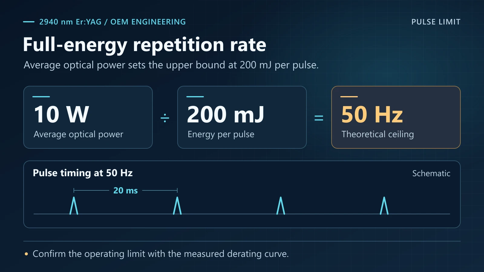
Where 50 Hz comes from. 200 mJ × 50 Hz = 10 W. At full energy the ceiling is set by the energy–power product; in practice it is also bounded by thermal load in the rod, so treat the number as a starting point and confirm it against a measured derating curve rather than extrapolating linearly. Running below full energy allows a higher rate.
For a scanning handpiece the pattern rate ceiling is spots per shot × repetition rate. Concretely: a 10 mm × 10 mm area at 1 mm pitch is a 10 × 10 grid, so 100 spots — two seconds at one spot per shot, before any overlap factor. Either each pulse covers more area, or the procedure takes longer. This is a mechanical and electronics input, and it is usually discovered late.
Why the 100–1500 ns range is worth having. The same 200 mJ delivered in 100 ns versus 1500 ns is a fifteen-fold difference in peak intensity at equal fluence. The thermal relaxation time of water near 3 µm is on the order of 1 µs: pulses shorter than that confine heat to the absorption layer, longer pulses let it diffuse. One head spanning both lets a single platform serve different handpieces and processes.
Two points must be confirmed against measurement rather than taken from the datasheet: the actual pulse waveform, since peak power depends on pulse shape and the rectangular assumption is only an order-of-magnitude estimate; and the pulse-width-versus-energy curve, because not every configuration reaches 200 mJ at the shortest setting. Get both before freezing the optical design.
3. Getting the beam to the handpiece
This is where most 2.94 µm projects stall, and the laser is rarely the cause. Ordinary silica fiber is effectively opaque here: the OH absorption band peaks almost exactly at 2.94 µm, and silica is already cut off above about 2.7 µm, with losses in the tens to hundreds of dB per metre.
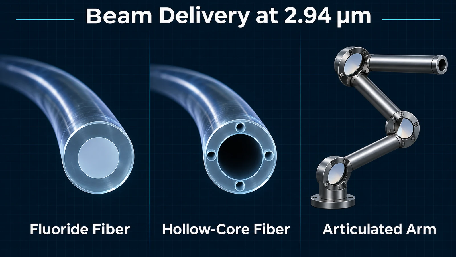
| Delivery method | Advantage | Penalty | Where it fits |
| Standard silica fiber | — | Opaque at 2.94 µm; tens to hundreds of dB/m | Not applicable |
| Low-OH silica fiber | Cheap, flexible, standard connectors | Still lossy; centimetre-scale runs at limited energy only | Short intra-handpiece links |
| Fluoride fiber (ZBLAN) | Loss as low as 0.02–0.15 dB/m at 3 µm | Hygroscopic, mechanically weak, damage-threshold limited, expensive | Short-to-medium flexible delivery |
| AlF₃-based fluoride fiber | Better damage resistance and moisture tolerance than ZBLAN | Scarce supply, higher cost, fewer core sizes | Higher-energy flexible delivery |
| Hollow-core fiber | No glass in the beam path; better damage threshold than solid-core fiber | Bending loss, large bend radius, less long-term reliability data | Handheld and endoscopic delivery |
| Articulated arm | No material absorption; highest energy capability | Rigid, heavy, alignment-sensitive, constrains ergonomics | Floor-standing fixed consoles |
Choose by whichever constraint hurts most. For a fixed console with a floor-standing arm, the articulated arm remains the most robust answer — there is no absorbing material in the path, only a few percent reflection loss per mirror. For handheld or endoscopic delivery, hollow-core fiber is the more interesting option now, and the specification to ask for is damage threshold, not insertion loss alone. Fluoride fiber wins on attenuation but loses on deliquescence and end-face damage, which becomes a replacement-cost line over a device's service life.
Coupling is the part most often treated as wiring. Three quantities have to agree: core diameter against beam divergence (too small and the end face exceeds its damage threshold; too large and flexibility suffers), numerical aperture against the handpiece input optics, and end-face power density — at 200 mJ into a small core, the end face usually fails before the fiber body does. Alignment and re-mating tolerances also belong on the drawing, because connector play at the handpiece turns directly into pulse-to-pulse variation. None of these figures are in the datasheet; confirm them with GK engineering against your actual optical path.
Whichever route you take, the delivery is part of the cavity's thermal environment. An end face that heats by tens of degrees changes coupling efficiency and transmission. Active connector cooling belongs in the mechanical design, not in a field fix after the adhesive discolours.
4. Lamp-pumped versus diode-pumped: the honest trade
The 2940-200mJ is lamp-pumped by design. It is worth being explicit about what that buys and costs, because buyers often compare the two architectures on the wrong axis.
| Dimension | Lamp-pumped | Diode-pumped |
| Pulse energy | High; 200 mJ class is straightforward | Limited by pump brightness and crystal size |
| Electrical-to-optical efficiency | Low; much of the input becomes heat | High |
| Pump source life | Flashlamp is a consumable, counted in shots | Long-life pump diodes |
| Repetition rate | Limited by thermal load in the rod | Higher |
| Beam quality | Multimode | Better; near-fundamental possible |
| Cost structure | Cheap per joule | 1.47 µm / 1.53 µm pump diodes are expensive |
| Field service | Technician replaces the lamp | Pump module swapped as a unit |
The decision rule is unglamorous: at 100 mJ or more per pulse and tens of hertz, lamp pumping stays the economical answer; at 20 mJ, 20 Hz in a compact enclosure, diode pumping wins on size and electrical draw. The first case optimises cost per millijoule, the second optimises wall power and heat. Both architectures produce good devices; the mistake is demanding lamp-pumped energy from a diode-pumped design, or diode-pumped efficiency from a lamp-pumped one.
Four requirements that should send you elsewhere early, before the mechanical design is fixed:
l 200 mJ and more than 50 Hz at the same time. The energy–power product is exceeded; it cannot be delivered in this architecture.
l Metre-scale flexible delivery at the full 200 mJ. Fluoride fiber is energy-limited and hollow-core brings bending and reliability penalties; there is no cheap answer for long runs at full energy.
l Fundamental-mode output with a spot a few micrometres across. Multimode plus homogenisation is designed for uniform-area ablation, not tight focusing.
l Continuous-wave output. This is a pulsed source; CW applications are outside its scope.
5. Thermal budget: size it from the wall, not from the beam
The head is rated for 10–30 °C ambient, 10–73 % RH non-condensing, and 86–106 kPa. The datasheet does not publish electrical input power, and no efficiency figure should be invented here — it depends on your pulse configuration and repetition rate, and has to be measured at your operating point.
Four steps that save a redesign:
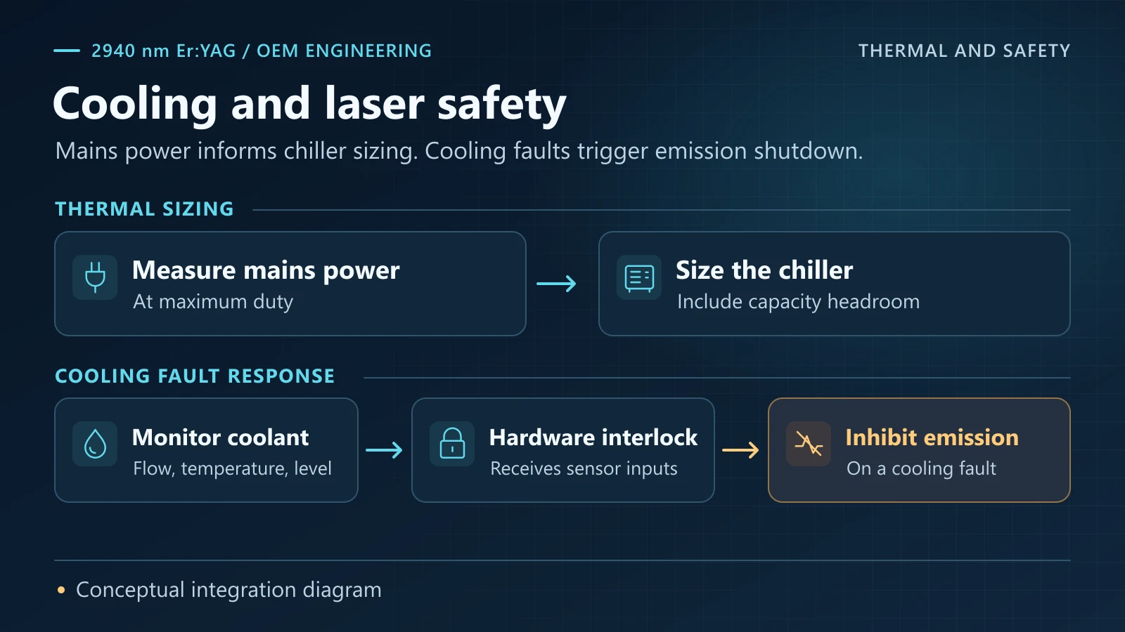
1. Measure electrical input at maximum duty, not at 10 Hz. Acceptance testing at low repetition rate is how chillers end up undersized at full load.
2. Add 30 % headroom to chiller capacity for enclosure heat and component aging.
3. Specify coolant temperature stability, not just flow. Rod thermal lensing tracks coolant temperature, and the resonator is not athermal; temperature drift becomes beam pointing and spot variation.
4. Draw the lamp access path into the cart now. The flashlamp is a scheduled replacement item, and service access blocked by a wall is a structural mistake.
The following items carry no datasheet figure. They are the builder's to define, and each one fails in the field if skipped:
l Coolant quality — deionised water, conductivity limit, filtration, and change interval. Uncontrolled water fouls the loop and algae cut the flow before anything else does.
l Interlocks — flow, temperature, and level all belong in the safety chain. Loss of cooling must stop emission, not just raise an alarm.
l Electrical — protective earth and leakage, mains voltage and frequency tolerance, EMC. The supply ships with the head, but the device's safety approval does not transfer with it.
l Transport and condensation — after moving from a cold store or a winter loading bay, let the enclosure reach room temperature before power-up; condensation inside the cavity means rework at best and damaged coatings at worst.
6. Safety and compliance duties on the integrator
At 2.94 µm the beam is invisible and water absorption is extreme, so energy landing on the cornea is absorbed in the surface layer. At 200 mJ per pulse and 10 W average, emission is far above the accessible-emission limit for Class 3B and will normally fall into Class 4 under IEC 60825-1. The final classification must be established by the device builder on the real optical path, housing, and apertures — a bare source parameter cannot be used as a class label, and a shield does not by itself justify a lower class — the class depends on interlock reliability and on whether emission is still accessible in service mode.
At minimum, the integrator has to implement:
l Housing and interlocks — any removable panel opens the emission path; interlocks belong in hardware and must not be bypassable in software.
l Key control and emission indicator — power on is not emission on; emission status must be visible at the operating position, and unauthorised personnel must not be able to start the source.
l Beam stop — a defined termination for three failure modes: handpiece detached, fiber broken, articulated arm misaligned. The stop material has to survive 200 mJ-class pulses.
l Labelling and documentation — warning labels and aperture markings per the final class, plus an instruction manual covering protective measures, service windows, and training prerequisites.
l Service mode — isolate emission and confirm discharge before lamp changes, fiber changes, or end-face cleaning; keep service mode separate from clinical mode.
This is not a hand-off of responsibility. What the source can supply is emission data and test reports; protection and classification must be completed on the real optical path. Without both halves, neither party's obligation is actually discharged.
7. Integration checklist
☐ Delivery method chosen against core size, energy per pulse, and bend radius
☐ Core diameter, beam divergence, numerical aperture, and end-face power density reconciled
☐ Repetition-rate ceiling reconciled with scanner pattern rate and procedure time
☐ Wall power measured at maximum duty; chiller sized with headroom
☐ Coolant quality and flow/temperature/level interlocks defined and wired into the safety chain
☐ On-device energy monitoring added if 5 % pulse-to-pulse variation is insufficient for the process
☐ Housing, hardware interlocks, key control, emission indicator, and beam stop implemented for the final optical path
☐ Laser-safety classification tested to IEC 60825-1; labels and manual updated accordingly
☐ Lamp access, consumable cost, and the service isolation procedure modelled over device life
☐ External trigger / sync requirements confirmed with GK engineering before freezing electronics
☐ Enclosure ambient held within 10–30 °C — outside that range the head is not rated
8. FAQ
Is 200 mJ at 10 W a fixed ratio?
At full energy, yes: 10 W ÷ 0.2 J gives 50 Hz. You can trade energy down for rate up, but you cannot have both at the datasheet maximums. Treat the derating curve as measured data, not a linear rule.
Can I run this off standard silica fiber?
Not over any useful length. 2.94 µm sits inside the OH absorption band, and silica is cut off above roughly 2.7 µm. Use low-OH silica for centimetre-scale links, fluoride or hollow-core fiber for flexible delivery, or an articulated arm.
Why multimode output?
Because the application is surface ablation, where a homogeneous spot is more controllable than a tight one: fewer hot spots, flatter crater floors. If your process needs a small focused spot, this architecture is the wrong starting point.
Does the head include the chiller?
No. The chiller is listed as a companion item; the head and the dedicated power supply are the two units supplied with the laser. Fiber and articulated arm are options as well.
What laser class will my device be?
That cannot be derived from the source parameters alone. At 200 mJ / 10 W the emission is well above the Class 3B limit and the device will normally be Class 4, but the class depends on the optical path, housing, and apertures, and must be determined by testing to IEC 60825-1. The source supplies emission data, not a classification.
Can it be synchronised to a scanner?
Trigger and synchronisation are configuration questions. Confirm them with GK engineering against your scan controller before freezing the electronics design. The datasheet does not publish interface specifications, so do not assume the capability.
Is this "cooling" the same as the Stirling cryocooler used with infrared detectors?
No. Here the coolant loop removes waste heat from the lamp and the rod at near-room temperature. A Stirling cryocooler takes an infrared detector down to the liquid-nitrogen range (about 77 K). Different purpose, different temperature range, different hardware — the Stirling Cryocoolers category on this site belongs to the latter, so do not treat the two as interchangeable when specifying.
9. Working with GK Semiconductor
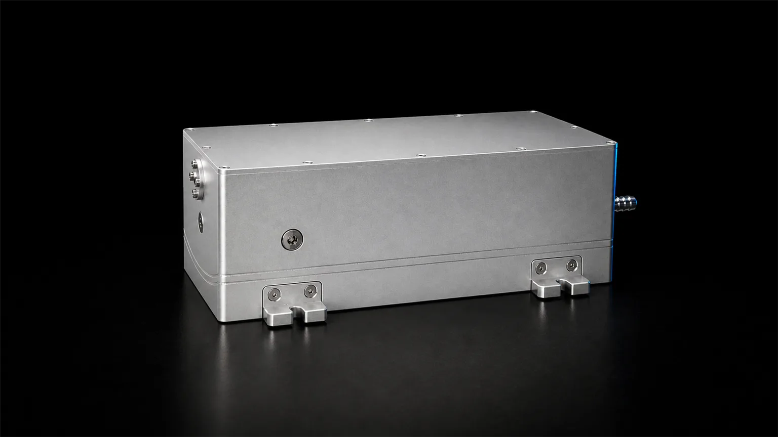
The 2940-200mJ ships in an integrable form: laser head, dedicated power supply, and a defined optical interface, leaving the handpiece, delivery, and enclosure to your design. Quotations are based on measured pulse energy and stability at your operating point, not catalogue maxima.
GK's laser portfolio spans more than a dozen bands from 780 nm to 2940 nm; the 2940 nm head is the option aimed at medical and aesthetic device builders. Material, chip, device, module, and system work sit inside one IDM flow, so process experience transfers across bands.
l Request datasheet and test report — pulse energy versus repetition rate, energy stability, beam profile, measured waveform.
l Inquire for an engineering sample — bench units for delivery-method qualification.
l Product page: 2940 nm Er:YAG laser, 200 mJ
l Compare across bands: 1940 nm 50 W module · 808 nm 300 W QCW bars · three-wavelength selection guide — note that 808 nm pumps Nd:YAG/Yb:YAG, not Er:YAG; the link is for band comparison only.
Sources and conventions. Device parameters come from the GK product manual, edition 0803 (2940 nm lamp-pumped Er:YAG page), and every device-level figure in this article follows that edition; re-check the section when the manual is revised. Values marked "derived" or "approximate" are calculated as P = E × f and P_peak = E ÷ τ, with peak power simplified to a rectangular pulse. Water absorption coefficients and penetration depths are taken from published literature (Biomedical Optics Express, 2018, 9(9):4552, Table 2; Photonics, 2024, 11(1):19, review of mid-infrared fiber power delivery) and are used to establish physical scale, not device specifications. Published 2026-11-09.